Table of Contents
Insulation resistance is a measure of how effectively an electrical insulating material prevents the flow of current through it. It is crucial in electrical systems to ensure safety and proper operation. It should be checked often so that cases of weak insulation can be early detected and weaker insulation can be replaced.
Definition of IR:
Insulation resistance (IR) is the electrical resistance offered by an insulating material to the flow of current through it. It is typically measured in ohms (Ω).
Purpose of IR:
Insulation resistance testing is conducted to assess the condition of electrical insulation in various equipment such as cables, transformers, motors, and generators. It helps identify potential issues like insulation breakdown or deterioration.
TYPES OF INSULATION RESISTANCE TESTS
Spot Reading Test:
This procedure to identify the insulation resistance gives a basic estimation of the insulation resistance for equipment that has less capacitance like panel wiring. In this process, a megaohmeter is connected across the insulation to be tested and a suitable test voltage is applied for a specified time generally 60 seconds. The reading of insulation resistance is thus noted. Any downward trend in the reading normally indicates deterioration in the insulation.
Time Resistance Test:
The time resistance test method is dependent on time as the name suggests. This is because in this process of testing the insulation resistance the megohmeter connected across the insulation shows a continuous increase in resistance of the insulation suggesting a good insulation. This happens because charges forming on the plate of capacitors attract opposite polarity of charges in the insulation and as these charges move, it results in drawing of current. Good insulation normally shows this effect of charge longer than the time taken to charge the capacitance of the insulation.
It is performed on large equipment of high voltage rating like transformers, motors, HV cables, etc. This method is also called the absorption test method as it relates to the absorption effect of healthy insulation.
Polarization Index PI test:
The polarization index or PI is the ratio of two-time resistance test values taken at 10 minutes to the value taken at 1 minute. The ratio of time resistance tests at 60 seconds to 30 seconds is called as a dielectric absorption ratio. Any polarization index value less than 1 should be thoroughly investigated as it suggests extremely poor insulation health. Below is a table as specified by ANSI.
| Insulation Condition | Dielectric Absorption Ratio | Polarization Index |
| Dangerous | Below 1.00 | |
| Questionable / Poor | 1.00 to 1.25 | 1.00 to 2.00 |
| Good | 1.40 to 1.60 | 2.00 to 4.00 |
| Excellent | Above 1.60 | Above 4.00 |
Measurement of IR:
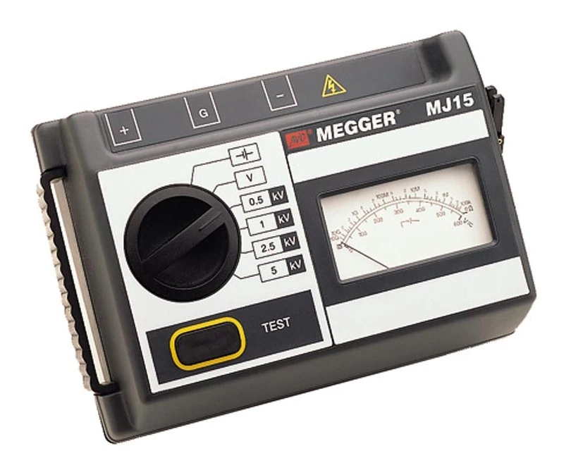
The insulation resistance is measured using a specialized instrument called an IR tester or megohmmeter. This device applies a high DC voltage (usually 500V, 1000V, or more) across the insulation and measures the resulting current. The resistance is then calculated using Ohm’s Law (Resistance = Voltage / Current).

Acceptable Values of IR:
The acceptable value varies depending on the type of equipment and the operating conditions. Generally, higher resistance values indicate better insulation conditions. Specific standards and guidelines (such as IEEE, IEC, or manufacturer specifications) provide recommended minimum resistance values for different equipment.
The rule may be stated: Insulation resistance should be approximately one megohm for every 1,000 volts of operating voltage, with a minimum value of one megohm.
The empherical formula is IRmin (in megohm) = Rated Voltage (in KV) + 1
However, the best IR value between phase to phase or phase to ground is considered to be infinite or in Giga-ohms in case of high voltage applications.

The insulation resistance between phase to neutral or neutral to ground or phase to phase of a LT system must be atleast 1MΩ. However for an HT system the phase to ground and other IR values should be in GΩ for healthy insulation.
Factors Affecting Insulation Resistance IR:
Insulation resistance can be affected by factors such as temperature, humidity, contamination, mechanical stress, and the age of the insulation material. An increase in temperature reduces the insulation resistance and vice-versa. Moisture or humidity also decreases the resistance of indulation. Contamination of the insulation at times prove to be fatal because of the formation of an ionization path along the surface which can result in a flashover of insulation. Therefore, it is important to conduct periodic testing to monitor the condition of electrical insulation and identify any potential deterioration before it leads to equipment failure or safety hazards.
Ensuring Electrical Safety through Insulation Resistance Testing
Insulation resistance testing is crucial for maintaining electrical safety in residential installations. It helps detect faults or weaknesses in insulation that could lead to hazards like electric shocks or fires. Here’s a step-by-step guide to conduct the test:
1. Safety Precautions
Before starting, ensure all circuits are de-energized and follow safety protocols, including wearing appropriate personal protective equipment (PPE). This is the most important thing when addressing any electrical equipment.
2. Equipment
Use a properly calibrated insulation resistance tester (megger) that is in good working condition.
3. Isolation
Completely isolate the circuit or equipment under test from the power supply. This may involve disconnecting it from the distribution board.
4. Discharge
Discharge any capacitors in the circuit to prevent potential shock hazards before connecting the insulation resistance tester.
5. Connections
Connect the tester leads correctly: one leads to the insulation and the other to the exposed conductor.
6. Test Voltage
Set the test voltage on the tester. Typically, for residential installations, use 500V or 1000V depending on requirements.
7. Testing
Initiate the insulation resistance test. The tester applies the selected voltage and measures the resistance. Ensure the measured resistance is well above the minimum specified (usually 1 to 2 megohms for residential installations).
8. Recording
Record the insulation resistance value obtained. Compare it with recommended minimum values and local regulations.
9. Interpretation
A high resistance value indicates good health of insulation. However, a gradual decrease in the resistance indicates the aging of the insulation and deterioration. A resistance value below the recommended minimum or sudden drop indicates a potential issue with the insulation. Further inspection and testing may be necessary to identify and resolve the problem.
10. Documentation
Document test results, including date, tested circuit/equipment, measured resistance, and any actions taken. In summary, insulation resistance is a critical parameter in ensuring the reliability and safety of electrical systems by assessing the quality and integrity of insulation materials used to prevent current leakage and ensure the proper functioning of electrical equipment.
Insulation Resistance Calculation
- Resistance of insulation = Applied Voltage / Leakage current
- Let us suppose that the applied voltage is 5000V and the leakage current is 0.05 mA.
- Therefore, the insulation resistance based on above formula will be
- = 5000/.00005 (converting mA to A) = 1000000 Ω = 1MΩ
This article is a part of the Testing and commissioning page, where other articles related to topic are discussed in details.

