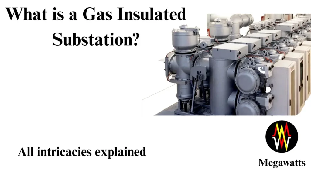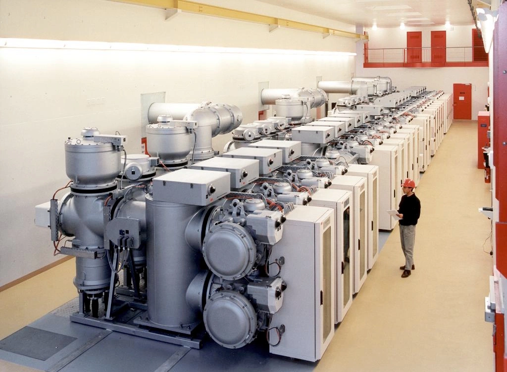
A GIS or gas-insulated switchgear substation is a compact, metal-enclosed structure that houses high-voltage switchgear, busbars, and other electrical equipment. Unlike conventional Air Insulated Switchgear (AIS) Substations, which use open-air configurations, GIS substations utilize sulfur hexafluoride (SF6) gas as an insulating medium within metal-enclosed units. This design not only reduces the space requirement of substations but also enhances operational reliability and safety.
Table of Contents

In the realm of modern electricity distribution, Gas Insulated Switchgear (GIS) Substations represent
a pivotal advancement. These sophisticated systems play a crucial role by enhancing the efficiency, reliability, and safety of power transmission across various applications.
Enclosure
The common enclosure material is an aluminum alloy which is chosen for an enhanced combination of mechanical strength, electrical conductivity, resistance to atmospheric corrosion, and reasonable price. Casting, extrusion, and wrought production methods are used to manufacture the enclosures, depending upon their application. For example, the enclosure of a complex heavy-duty switch may be cast aluminum and a bus enclosure may be extruded. Enclosure parts are also welded together sometimes.
COMPARTMENTALIZATION REQUIREMENTS
The components of the GIS substations come directly fitted in modules from the factory or the manufacturer. The assembly consists of separate modular compartments filled with gas and in a gas-tight partition so that maintenance in one feeder can be done without de-energizing the adjacent feeder. The compartmentalization is done to isolate the faulty section.
Phase segregation
All three phases can be assembled in a common metal enclosure or can be segregated in a separate metal enclosure depending upon cost consideration and three-phase fault rating value. In common practice, it is seen that up to 170 KV GIS no phase segregation is preferred. Functionally the performance does not differ between three enclosures and a single enclosure.
GAS BARRIERS
To reduce the damaged area by a fault and to improve maintenance flexibility the GIS enclosure is subdivided into several compartments and the enclosure, gas barriers are used and are color-coded in orange or yellow color.
The Gas barrier is also called a resistant spacer which divides the bay into separate gas compartments that are sealed off from each other.
Acceessories
Flange joints that connect separate modules contain gaskets to prevent the leakage of gas. Therefore gas monitoring devices are installed for each compartment of the GIS enclosure.
For non-switching compartments like CT, 1 Partial Discharge sensor is normally used at every 20-meter distance.
For Switching compartments like disconnectors, circuit breakers, etc 1 PD sensor is used for each module.
For each isolated gas compartment, 1 Gas density monitor is used, which indicates the density of the gas.
Space heaters are used in LCC panels and other cubicles.
In every gas compartment, 1 pressure relief device is installed. This device is installed to protect the main gas enclosure under the worst operating conditions and abnormal pressure rise which may be generated due to internal fault arcs. Although a protection system will interrupt the fault before a dangerous pressure is reached, PRD is used as a backup enclosure protection.
Each gas chamber is equipped with an absorber to remove the moisture and decomposed products from the gas chamber.
Advantages
The adoption of Gas Insulated Switchgear substations brings several compelling advantages:
Low area requirement Of GIS. Gis substations take a fraction of space as the same specification Ais substation will take. The fraction can be ranging from 1/10 to 1/25. The height of the substation is also reduced compared to the AIS substation’s switchyard.
Environmental adaptability of GIS. Gas Insulated Switchgear is suitable for installation almost anywhere in or out of doors, even underground, near the sea, in mountainous areas, in regions with heavy snowfall, etc.
High-margin safety of GIS. The high-voltage conductors are safely and securely enclosed in a grounded metal enclosure which enhances the margin of safety.
High reliability of GIS. The chemically inert SF6 enveloping the conductors and insulators preserves them for years of trouble-free operation.
Long maintenance intervals of GIS. SF6 gas’s arc-quenching properties reduce contact wear. Technological advancements over the years have seen Gas Insulated Switchgear continue to grow smaller and lighter.
Low Maintenance Cost of GIS: Gas Insulated Switchgear is highly reliable and maintenance-free. No inspection is required before ten years.
Long Life of GIS: The operating life of Gas Insulated Switchgear is 40 to 50 years compared to 25 to 30 years of conventional outdoor grid stations.
Personnel Safety in GIS: Gas Insulated Switchgear causes no risk of injury to operating personnel.
Short Circuits by Wildlife: Fully encapsulated enclosures reduce the risk of outages caused by lizards and vandalism.
Unbeatable Performance: Factory-assembled and tested units offer unbeatable performance in terms of reliability and continuity of power supply.
Unaffected by Environmental Conditions: Gas Insulated Switchgear is unaffected by environmental factors. It is most suitable for rough environmental conditions i.e. humid, saline, polluted atmospheric air where industrial exhausts are maximum.
Economical: GIS plants are more economical than conventional counterparts despite the high cost of Gas-insulated switchgear.
Applications and Deployment
Gas Insulated Switchgear substations find wide-ranging applications across various sectors:
Utility Sector: Integral to high voltage transmission and distribution networks, Gas Insulated Switchgear substations optimize grid efficiency and reliability.
Industrial Sector: Deployed in industrial complexes and critical facilities, Gas Insulated Switchgear substations ensure uninterrupted power supply and operational continuity.
Maintenance and Operational Considerations
Routine maintenance of Gas Insulated Switchgear substations involves periodic inspections, SF6 gas monitoring, and adherence to safety protocols. Emergency response procedures are meticulously planned to address any gas leaks or operational faults promptly, ensuring minimal disruption to the power supply.
SF6 Properties
Physical
The compound Sulphur hexafluoride has a density of 6.16 g/l and 760 torr at room temperature and pressure, which is five times heavier than air. The critical temperature of the gas is about 45.6 degrees Celsius and hence can be easily liquified by compression. The gas is colorless and odorless.
Since the gas is heavier, therefore it must be taken care that sufficient ventilation is provided in the workplace. Also, the personnel must be made aware of the danger of asphyxiation (lack of oxygen) in places without proper ventilation.
Electrical
The gas is electronegative and thus it attracts free electrons. The arc quenching properties of the gas is adequate and the dielectric strength of around 90 KV/cm which is 2.5 to 3 times that of nitrogen or air at atmospheric pressure and usual test conditions.
Maximum Acceptable Impurity Level
Under ambient conditions 100kpa and 20 degrees Celsius,
- The air present should be limited to 2 g/kg which is equivalent to 1% volume.
- CF4 should be limited to 2400 mg/kg, equivalent to 4000 μl/l.
- Water content should be limited to 25 mg/kg, equivalent to 200 μl/l.
- Mineral oil 10 mg/kg, equivalent to 73 μl/l
- Total acidity expressed in HF must be limited to 1 mg/kg, equivalent to 7.3 μl/l.
Due to the maximum impurities, the amount of SF6 gas in a container shall be higher than 99.7% in weight measured in the liquid phase.
Difference between AIS and GIS substation
| AIS substation | GIS substaion |
| Insulation of live parts is done by air. | Insulation of live parts is done by gas like SF6 |
| Requires a large area to be built. | Smaller area requirement. |
| The initial cost is low. | Pollution has minimal effect. Almost negligible. |
| The initial cost is high. | Initial cost is high. |
| High maintenance is required. | Low maintenance is needed. |
| High risk of accidents. | Low risk of injury and accidents. |
Future Trends and Innovations
As technology evolves, GIS substations are poised to evolve as well:
Eco-friendly Alternatives: Ongoing research focuses on developing environmentally sustainable alternatives to SF6 gas, aligning with global initiatives for reducing greenhouse gas emissions.
Smart Grid Integration: Integration with smart grid technologies enhances the flexibility and efficiency of GIS substations, paving the way for real-time monitoring and grid management.
Conclusion:
GIS substations represent a paradigm shift in the field of power distribution, offering compactness, reliability, and safety unparalleled by traditional substations. As demands on electricity infrastructure grow, GIS technology continues to play a pivotal role in advancing the reliability and efficiency of power networks worldwide. Embracing GIS substations not only addresses current challenges but also positions us favorably for a sustainable and resilient energy future.
This article is a part of the Substation Guide, where other articles related to substation are discussed in details.

