A protective relay works like a brain in the power system. It collects the electrical parameters from the field and computes them, senses faults, takes decisions, and gives output to the associated circuit breaker to isolate the faulted section.
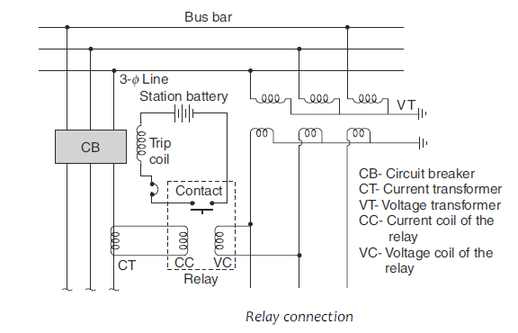
Protective relays can be broadly classified into three types.
Electromechanical protective relay
Static protective relay
Numerical protective relay
Table of Contents
Electromechanical relay
These are the protective relays that use the electromagnetic or thermal forces generated by the input electrical parameters on the moving part to operate. The mechanical force thus results in the movement of the moving part and closes or opens a contact for relay operations. The contacts can be wired for the desired operation. Since mechanical torque is generated by electricity/current, this arrangement is called an electromechanical relay.
Most electromechanical protective relay uses magnetic attraction or induction caused by the flow of electric current into the coil for their operation also termed as electromagnetic relays. Some electromechanical relay also uses electrothermic principles for their operations such as the use of bimetallic elements which utilize their thermal expansion based on temperature rise and push a plunger to trip a circuit.
The most widely used electromechanical relays are
- Attracted armature relay
- Induction relay
- Thermal relay
Attracted armature relay
Attracted armature relays are the simplest type that respond to both types of current alternate as well as direct. These relays operate through an armature that is attracted to an electromagnet or through a plunger that is drawn into a solenoid. All these protective relays use the same electromagnetic attraction principle for their operation. The electromagnetic force exerted on the armature or the plunger is directly proportional to the flux squared in the air gap or in other words to the current squared.
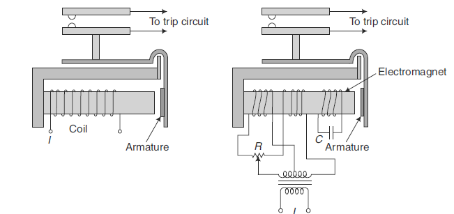
In DC relays, however, this force is constant. In the case of AC relays, the total electromagnetic force pulsates at double the frequency. The motion of the moving element is controlled by a counter force which acts due to gravity or a counter spring force.
The different types of construction of attracted armature relays are:
- Hinged armature type
- Plunger type
- Balanced beam type
- Moving-coil type
- Polarised moving-iron type
- Reed type
Induction Relays
Induction relays use the electromagnetic induction principle for their operation. Their principle of operation is the same as that of a single-phase induction motor. Hence, they can be operated using AC currents only. Two types of construction of these protective relays are standard: one with an induction disc and the other with an induction cup. In both types of relays, the moving element (either disc or cup) is equivalent to the rotor of an induction motor. There is however, one contrast from the induction motor, i.e., the associated iron with the rotor in the relay is stationary contrary to the motor.
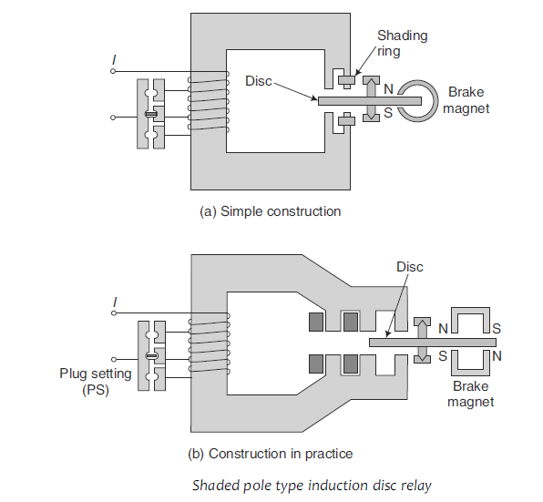
The moving element carries the rotor currents, whereas the stationary magnetic elements complete the magnetic circuit. Two sources of alternating magnetic flux in which the moving element may turn are required for the operation of induction-type protective relays. For generation of the operating torque, there must be a phase difference between the two fluxes. There are two types of construction of induction disc relays, namely the shaded pole type and the watt-hour meter type.
Thermal Relays
These relays utilize the electro-thermal effect of the actuating current for their operation. They are used to protect the motors against overloading and unbalanced currents. The thermal element is basically a bimetallic strip, usually wound into a spiral to obtain a large length which increases the sensitivity as a result.
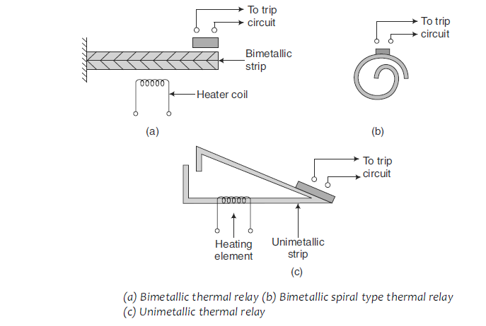
A bimetallic element consists of two metal strips of varying coefficients of thermal expansion. When the element is heated one strip expands more than the other. This generates the bending of the strip. The thermal element gets heated directly by passing the actuating current through the strip, but usually, a heater coil is employed for heating. When the bimetallic element heats up, bending and deflecting, ultimately closing the relay contacts.
Auxiliary Relay, Auxiliary Switch and Flag
A protective relay is assisted by auxiliary relays for a number of important operations. A protective relay measures the parameter and under the required condition, closes its contacts. It is relieved of other duties such as tripping, time lag, breaking of trip circuit current, giving the alarm, showing flags, etc.
These duties are performed by auxiliary relays. Auxiliary relays function to repeat the operation of protective relays, control switches, etc. Repeat contact and auxiliary switches are also used to assist protective relays. The reasons for employing auxiliary relays, repeat contractors, and auxiliary switches are:
- Protective relay contacts are delicate and light in weight. They are not capable of carrying large amounts of current for a long period.
- The protective relays often do not have the number of contacts required to perform all duties required in the protection scheme.
The most common auxiliary relays are described below.
Seal-in Relay
A seal-in relay is an auxiliary relay that is employed to protect the contacts of a protective relay. Once the protective relay closes its contacts, the seal-in relay gets actuated. Its contacts bypass the contacts of the protective relay and close and seal the circuit while the tripping current flows. It also gives an indication by showing a flag. It is an instantaneous relay, that operates on the attracted armature principle.
Time-lag Relays
Time-lag relays operate after a preset time-lag. They are used in protection schemes as a means of time discrimination, for example, time-graded schemes. They are also used in control and alarm circuits to allow time for the required sequence of operations to take place.
Alarm Relays
An alarm relay gives both an audible and a visual indication. At a substation, it is sufficient to provide a trip alarm and one non-trip alarm, which is common to the whole substation. In the control room of a generating station, the trip alarm and non-trip alarm should be separate for each primary circuit. There is an arrangement for alarm cancellation by pressing a button. The alarm circuit is interrupted by pushing this button. When the relay is de-energized, the initiating contact of the cancellation mechanism is reset so that it can receive another alarm.
Repeat Contactors
A repeat contactor repeats the operation of a protective relay. It is sometimes needed because a protective relay may not have enough contacts. It may also be required to take over the operation from the initiating relay if the contacts of the latter are not designed for carrying current for long periods. Its most important requirements are that it should be fast and reliable. It should also be robust and compact. It is usually mounted in the same case as the relay for which it is required to repeat the operation.
Repeat contactors operate on the attracted armature principle. It may be connected either in series or in parallel with the relay. It contains a few contacts which are placed in parallel. However, having more than three contacts in parallel is usually not practical.
Flag or Target
When a relay operates, a flag is indicated to show its operation. When on a relay panel there are several relays, it is the flag that indicates, the relay that has operated. This helps the operator to know the cause of the tripping of the circuit breaker. It is also called the target or indicator. Its coil is connected in series with the trip coil of the circuit breaker. The resetting of a flag indicator is usually manual. There is a button or knob outside the relay case to reset the flag indicator.
A flag indicator may either be electrical or mechanical. In a mechanical flag indicator, the movement of the armature of the relay pushes a small shutter to expose the flag. In an electrically operated flag indicator, there is a solenoid that is energized when relay contacts are closed. Electrical flags being more reliable are preferred.
Auxiliary Switch
An auxiliary switch is connected in series with the trip-coil circuit. It is mechanically interlocked with the operating mechanism of the circuit breaker so that the auxiliary switch opens when the circuit breaker opens. The opening of the auxiliary switch prevents unnecessary drainage of the battery. When the trip-coil of the circuit breaker is energized, it actuates a mechanism of the circuit breaker, which causes the operating force to come into action to open the circuit breaker.
Connections for Seal-in Relay, Auxiliary Switch, and Circuit Breaker Trip-Coil
The connection for a seal-in relay, circuit breaker trip-coil, and auxiliary switch is shown below. To protect the contacts of the protective relay, a seal-in relay is employed. Its contacts bypass the contacts of the protective relay and seal the circuit closed, while the tripping current flows. Some relays employ a simple holding coil in series with the relay contacts.
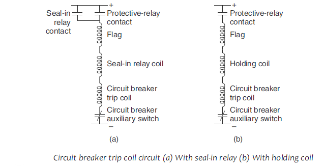
The holding coil is wound on a small soft iron core which acts on a small armature on the moving contacts assembly to hold the contacts tightly closed, once they have established the flow of current through the trip coil. The holding coils are used to protect the relay contacts against damage that may be caused due to the make-and-break action of the contacts.
STATIC RELAY
In a static relay, the comparison or measurement of electrical quantities is performed by a static circuit which gives an output signal for the tripping of a circuit breaker. Most of the present-day static relays include a DC polarised relay as a slave relay. The slave relay is an output device and does not perform the function of comparison or measurement. It simply closes contacts. It is used because of its low cost. In a fully static relay, a thyristor is used in place of the electromagnetic slave relay.
The electromechanical relay used as a slave relay provides a number of output contacts at a low cost. Electromagnetic multi-contact tripping arrangements are much simpler than an equivalent group of thyristor circuits.
A static relay (or solid state relay) employs semiconductor diodes, transistors, zener diodes, thyristors, logic gates, etc. as its components. Nowadays, integrated circuits are being used in place of transistors. They are more reliable and compact.
Earlier, induction cup units were widely used for distance and directional relays. Later these were replaced by rectifier bridge-type static relays which employed DC polarised relays as slave relays. Where overcurrent relays are needed, induction disc relays are in universal use throughout the world. But ultimately static relays will supersede all electromagnetic relays, except the attracted armature relays and DC polarised relays as these relays can control many circuits at low costs.
Merits and Demerits of Static Relays
Merits
- Low burden on CTs and VTs. The static relays consume less power and in most of cases, they draw power from the auxiliary DC supply.
- Fast response
- Long life
- High resistance to shock and vibration
- Less maintenance due to the absence of moving parts and bearings
- Frequent operations cause no deterioration
- Quick resetting and absence of overshoot
- Compact size
- Greater sensitivity as amplification can be provided easily
- Complex relaying characteristics can easily be obtained
- Logic circuits can be used for complex protective schemes. The logic circuit may make decisions to operate under certain conditions and not to operate under other conditions.
Demerits
- Static relays are temperature-sensitive. Their characteristics may vary with the variation of temperature. Temperature compensation can be made by using thermistors and by using digital techniques for measurements, etc.
- Static relays are sensitive to voltage transients. The semiconductor components may get damaged due to voltage spikes. Filters and shielding can be used for their protection against voltage spikes.
- Static relays need an auxiliary power supply. This can however be easily supplied by a battery or a stabilized power supply.
NUMERICAL RELAYS
With the tremendous developments in VLSI and computer hardware technology, microprocessors that appeared in the seventies have evolved and made remarkable progress in recent years. Fast and sophisticated microprocessors, microcontrollers, and digital signal processors (DSPs) are available today at low prices. Their application to power system protection has resulted in the availability of compact, faster, more accurate, flexible, and reliable protective relays, as compared to the conventional ones.
In these protective relays, the analog current and voltage signals, monitored through primary transducers (CTs and VTs) are conditioned, sampled at specified instants of time, and converted to digital form for numerical manipulation, display, and recording. Thus, numerical relays, having monitored the current and voltage signals through transducers, acquire the sequential samples of these ac quantities in numeric (digital) data form, through the data acquisition system DAS, and process the data numerically using an algorithm to calculate the fault discriminants and make trip decisions.
With the continuous reduction in digital circuit costs and increases in their functionality, considerable cost-benefit improvement ensues. At present microprocessor/ microcontroller-based numerical relays are widely used. There is a growing trend to develop and use numerical protective relays for the protection of various components of the modern complex power system. Numerical relaying has become a viable alternative to the traditional relaying systems employing electromechanical and static relays. Intelligent numerical relays using artificial intelligence techniques such as artificial neural networks (ANNs) and Fuzzy Logic Systems are presently in active research and development stages.
The main features of numerical relays are their economy, compactness, flexibility, reliability, self-monitoring and self-checking capability, adaptive capability, multiple functions, metering and communication facilities, low burden on transducers (instrument transformers), and improved performance over conventional relays.
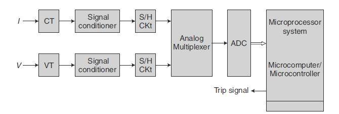
The levels of voltage and current signals of the power system are reduced by voltage and current transformers (VT and CT). The outputs of the CT and VT transducers are applied to the signal conditioner which brings real-world signals into the digitizer.
The signal conditioner electrically isolates the relay from the power system, reduces the level of the input voltage, converts current to equivalent voltage, and removes high-frequency components from the signals using analog filters.
The output of the signal conditioner is applied to the analog interface, which includes sample and hold (S/H) circuits, analog multiplexers, and analog-to-digital (A/D) converters.
These components sample the reduced-level signals and convert their analog levels to equivalent numbers that are stored in memory for processing.
The signal conditioner, and the analog interface (i.e., S/H CKt, analog multiplexer, and A/D converter) constitute the data acquisition system (DAS). The acquired signals in the form of discrete numbers are processed by a numerical relaying algorithm to calculate the fault discriminants and make trip decisions. If there is a fault within the defined protective zone, a trip signal is issued to the circuit breaker.
COMPARISON BETWEEN ELECTROMECHANICAL RELAYS AND NUMERICAL RELAYS
| SL NO | FEATURES | ELECTROMECHANICAL | NUMERICAL |
| 1 | Size | Bulky | Compact |
| 2 | Characteristics | Fixed | Selectable |
| 3 | Flexibility | Not Flexible | Flexible because of programming |
| 4 | Communication feature | Not available | Available |
| 5 | Blocking feature | Not available | Available |
| 6 | Self-supervision | Not available | Available |
| 7 | Adaptibility | Not adaptable | Adaptable to changing system conditions |
| 8 | Speed of operation | Slow | Very Fast |
| 9 | CT, VT Burden | Very High | Extremely Low |
| 10 | Consistency of calibration | Deteriorate with time | No deterioration even after 20 years of service |
| 11 | Settings | Through Plug settings in fixed steps | Software based |
| 12 | Memory feature | Not available | Several memory features available |
| 13 | Maintenance | Frequent maintenance is required | Maintenance free |
| 14 | Output relay programming | Not available | Available |
| 15 | Accessibility of relay from remote place | Several memory features are available | Remote accessibility is available |
This article is a part of the Protection System, where other articles related to the protection of electrical equipments are discussed in details.

