Distance protection is basically a non-unit form of protection in the power system that protects a transmission line by sensing and comparing the impedance to a set impedance value of the line. It is economical and has technical benefits. Unlike the phase, neutral overcurrent protection the main advantage of distance relay protection is that the fault coverage of the protected circuit does not depend on the source impedance variations.
Table of Contents
The basic principle
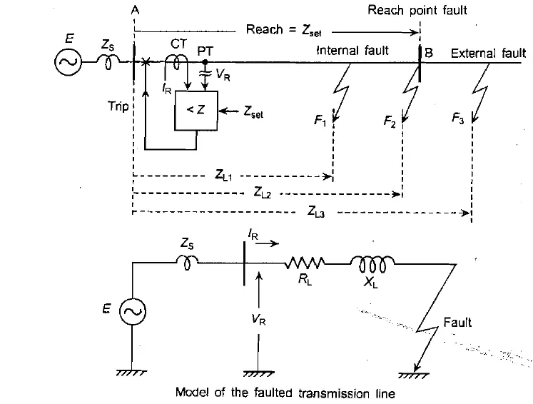
The basic principle of distance protection is impedance measurement at the relay location, which is voltage/current. The measured impedance value is then compared with reach point impedance, which is a preset value. A fault is percieved in the line when the measured impedance at relay point becomes less than the preset or reach point impedance.
Let AB be a transmission line with a single source at the A end. The extended protection zone is till B. The distance relay is present at the A end, where the local current and voltage are fetched from CT and PT at A. Assume that the voltage-to-current ratio is 1 for simplicity.

The reach of the distance relay is thus made to be Zset. The line AB is modeled as an R-L circuit so that high accuracy is achieved via relaying.
Now let’s consider three faults: an internal fault at F1, an external fault at F3, and a fault at the reach point fault at F2. Comparing the relay voltage VR with the product of relay current IR and Z, for all three faults.
- For F3, External current is IR3 and voltage is VR3, therefore VR3 > IR3 x Zset
- For F2, External current is IR2 and voltage is VR2, therefore VR2 = IR2 x Zset
- For F1, External current is IR1 and voltage is VR1, therefore VR1 = IR1 x Zset
Now the desired response of the relay will be
- to restrain from clearing the fault in case of F3,
- on the verge of tripping in case of F2, and
- will generate the trip signal in case of F1

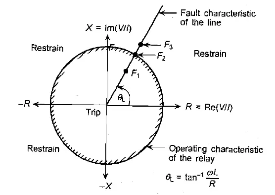
Thus the trip logic for the above can be written as, if VR < IR x Zset then trip else restrain.
The equation VR < IR x Zset can also be written as VR/IR < Zset. However, the ratio of VR/IR can be written as ZR
The relay, therefore must compute the impedance, seen from its location and compare it with a set value to make the trip decision. Because of the simple series model of the transmission line, the line impedance is directly proportional to the distance to the fault. Hence the relay is called a distance relay. Distance relays are also termed as under-impedance relays, however in practice, the word under is ignored and called an impedance relay.
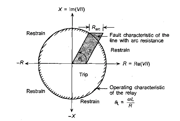
When we consider the arc resistance as in practice most faults contain the arc, the fault characteristic of the transmission line gets modified from a straight line with a slope to an area as shown.

Zones of Distance protection:
In order to provide reliability, the distance protection relay is divided into several zones:
Zone 1
It is intended to cover 80% of the protected line and is set to operate instantaneously with no intention of time delay. For numerical distance relays, settings of up to 85% can be considered safe. The remaining 15-20 % margin makes sure that the Zone 1 protection does not over-reaches the protected line due to errors from sensing trafos to inaccuracies in line impedance data, and relay setting errors. Otherwise, the relay will fail to discriminate the fast operating protection on the very line section.
Zone 2
The Zone 2 protection is kept at 120% of the protected line impedance for providing full protection to the protected line with additional margin for source faults. It provides backup for the faults on the shortest adjoining lines. It is also set to cover remote end bus bar faults. Hence it is called an over-reach element.
Zone 3
Primarily set to provide backup against external uncleared faults and hence it is set to cover the entire line along with the longest adjoining line in the remote end. Zone 3 provides remote backup protection for electrical faults on adjacent lines that is time-delayed for the discrimination.
Relay Performance
The performance of the distance relay depends upon the reach accuracy and operating time.
Reach accuracy
Reach accuracy is the measure of how closely the actual ohmic reach of the distance protection relay under practical conditions agrees with the relay setting value in ohms. In other words, it is the difference between the measured fault point and the real-world fault point. For example,
As the distance relay is usually set to cover 80% of a 100 km transmission line (say). But in the real-world scenario, it only covers 79 km. Therefore, there is an error of 1Km. Then the reach accuracy will be = 1/80 = 1.25%.
Reach accuracy particularly depends on
- CT and PT accuracy at the time of fault
- Internal error of the relay
- changes in the line impedance because of temperature and sagging
- fault resistance
Operating time
The operating time of the distance relay depends upon the fault current, the fault position relative to the preset, and the voltage at that instant.
| Zone | Operating Time |
|---|---|
| Zone 1 (closest zone) | Instantaneous (usually < 30 ms) |
| Zone 2 (backup zone) | Delayed (like 300 – 500 ms) |
| Zone 3 (remote backup) | Longer delay (like 800 ms – 1.5 sec) |
The inefficiencies of CVTs or due to saturation in CTs, relay operation can get delayed for faults near the remote end of the protected line.
Characteristics of Distance Protection Relay
Impedance Characteristics
This characteristic defines non-directionality with a circular shape in the R-X plane (resistance vs reactance) with a simple logic of tripping if the impedance is less than the preset. It is susceptible to load encroachment and power swings as load conditions may sometimes fall within the zone and cause false tripping.
Reactance Characteristics
It is good for use in short transmission lines and near the source, however, it lacks directional sensing and therefore needs to be clubbed with a directional element. It lacks resistance sensing and hence is good for close arcing faults.
MHO Characteristics
A MHO relay measures a component of admittance. But its characteristic, when plotted on the R-X diagram, it is a circle, passing through the origin. It has directional bias and detects faults only in the forward direction. It is much resistant to load encroachment and thus used in extra-high-voltage transmission lines.
| Functions | Impedance characteristics | Reactance characteristics | Mho characteristics |
| Measurements | Impedance, Z | Reactance, X | Impedance and angle |
| Shape in R-X diagram | Circle with center origin | Parallel line to axis of reactance | Circle with a center origin |
| Directionality bias | Non-directional | The circle passing through origin | Directional |
| Load encroachment | High | Can be, if X overlaps load region | Low |
| Zones | Zone 1,2,3 | Zone 1 | Obsolete, sometimes for backup zone |
| Applications | EHV transmission lines | Short transmission lines | Non-directional |
Other functions of Distance protection relay
Power Swing Blocking
Distance protection relay operates by detection of impedance in its zone, and sometimes voltage and current in the system are disturbed by fault. System impedance also changes and if the impedance moves into the relay’s zone it will trip. To prevent this situation, the distance protection relay uses PSB. By detecting the rate of change of the impedance, the relay will know which one is a fault and which one is a power swing, and block itself from tripping. It may be noted that the slow and smooth change in impedance is due to power swing and sudden and sharp change is considered to be a fault.
Fuse failure
PT fuse blows can make distance relay see ‘zero impedance’ despite no fault in the high voltage system. Distance relays use the ‘zero sequence concept’, by evaluating the zero sequence voltage distance relays can protect themselves from misoperation. In some modern distance relays PT fuse monitoring circuit directly supervises the PT circuit for fuse failure detection and alarm.
Switch On to Fault (SOTF)
For safety in transmission line maintenance, all three phases are grounded. After finishing the maintenance work, sometimes ground wires are forgotten to be removed from the line. When CB is closed, it closes on to fault. Distance relay use healthy voltage for reference, so when we close into 3-phase faults, no voltage reference will be there at all. There is chances of all zones not being tripped. Therefore, with Memory function, high-speed trips are initiated instead. It is the SOTF function of distance protection relay 21.
When the CB closes on to a fault
- Distance protection relay experiences a sudden drop in the impedance.
- Relay enters a time delay and monitors the impedance.
- If the impedance recovers back, then it may be due to switching transients, and the relay blocks further tripping, otherwise, at persisting dropped impedance, the relay considers it to be a fault and trips on SOTF.
Fault locator
It is connected in series with the main relay and records the distance between the relay point and the point of fault in terms of Z in Ohms, or length in KM, or percentage of line length. It receives the same inputs as the distance relay. Since the impedance of the line is proportional to the distance of the line, the measurement is initiated by a trip signal from distance relays. The fault locator therefore gives out the precise fault location, thereby greatly reducing the restoration time.
FAQ’s
What is the reach of the distance protection relay?
A distance protection relay operates when the measured impedance as measured by the relay is less than the preset value of the relay. This preset impedance or related distance is called the reach of the relay.
What is under reach of the distance protection relay?
When a distance relay fails to operate even when the fault point is within its reach it is called under-reach of the relay.
What is the main reason for under-reach in distance protection?
The presence of arc resistance is the main reason behind underreach.
This article is a part of the Protection System, where other articles related to the protection of electrical equipments are discussed in details.

