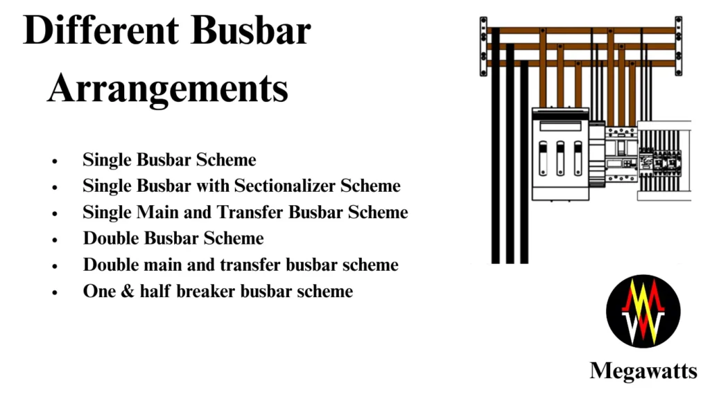
Bus bar
The bus bar is a common conductor/group of conductors where all incoming and outgoing feeders connect. It collects the incoming electrical power and distributes it to the outgoing circuits. We can say it works on Kirchhoff’s current law.
Table of Contents
The bus bar is used at all voltage-level substations and plants. For indoor installations copper/aluminum bars are used. For outdoor installations, ACSR conductors or aluminum tubes are used.
Different types of bus bar systems are utilized as per requirement & the selection of any busbar system depends upon the following points:
1. Amount of flexibility required in operation.
2. Initial cost of the installation.
OUTDOOR BUSBAR
These are normally used in outdoor substation AIS type.

INDOOR BUSBAR
These are bus bars that are installed inside a panel air-insulated type or can be seen inside gas ducts of GIS substation.
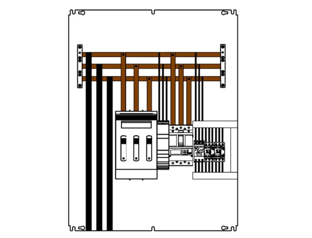
There are six types of busbar systems or schemes that are used extensively in the power industry.
- Single Busbar Scheme
- Single Busbar with Sectionalizer Scheme
- Single Main and Transfer Busbar Scheme
- Double Busbar Scheme
- Double main and transfer busbar scheme
- One & half breaker busbar scheme
Single Busbar Scheme:
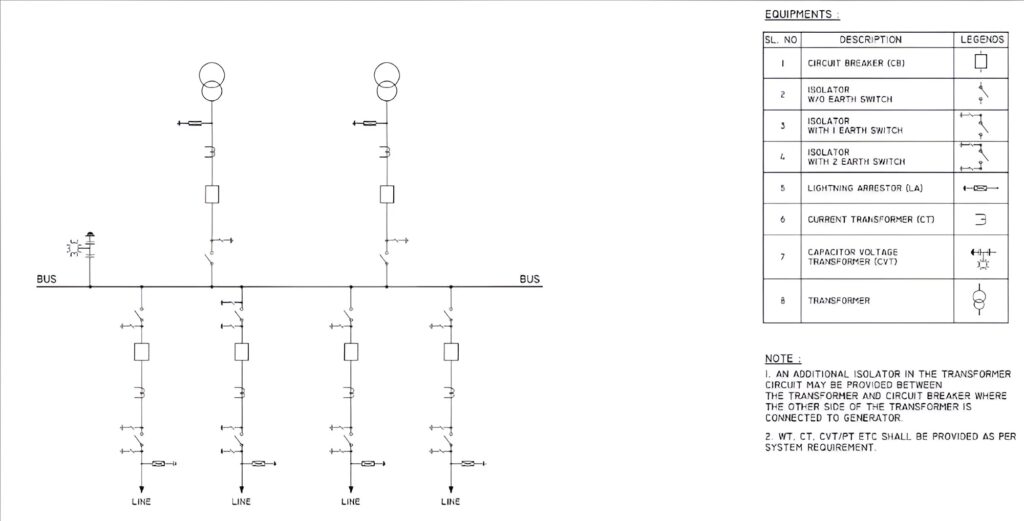
In the single busbar arrangement, the lines, and transformers are connected via one busbar
disconnector and one circuit breaker to one common busbar, and it is commonly used for a step-down (HV/MV) substation in the distribution network. This type of system has only one electrical common main bus bar.
Advantages:
· Simple and economical to design and install.
· Requires less space and fewer components.
· Easy to operate and maintain.
Disadvantages:
· If any fault occurs in this, the whole distribution of power is interrupted, and the feeder will be disconnected.
· Bus Bar maintenance causes high power interruption.
· Circuit Breaker maintenance causes high power interruption of the associated feeder.
Single Busbar with Sectionalizer Scheme:

Single Busbar: All incoming and outgoing feeders are connected to a single main busbar.
Sectionalizers: Sectionalizers are installed at strategic points along the feeders connected to
the busbar. The sectionalizers are essentially Circuit breakers that isolate the faulted section while maintaining supply to the rest of the system. They allow for selective isolation of faulted portions without affecting the entire system.
Advantages:
· Easy to remove the fault section without any loss in the critical supply continuity
· Individual sections on the bus can be repaired without disturbing the overall section on the busbar.
Disadvantages:
· Circuit breaker maintenance will cause an interruption in the associated feeder.
Single main and transfer bus scheme:

Main Bus: This is the primary busbar where the main power sources are connected.
Transfer Bus: This is a secondary busbar that is normally connected to the main bus through a bus
coupler comprising disconnectors/isolators, a circuit breaker, and a current transformer.
Advantages:
The additional provision of one transfer bus facilitates taking out one circuit breaker at a time for overhaul and maintenance without de-energizing the circuit controlled by that breaker. The same circuit can be energized by a transfer bus coupler breaker and transfer bus.
Disadvantages:
· Same as the single bus scheme, this scheme also suffers from the disadvantage that in the event of a fault in the main bus, there will be a complete shutdown of the substation.
· Transfer bus coupler can take care of maintenance in only one feeder without power interruption.
Double Busbar Scheme:

In this scheme, a double bus bar is provided, and each circuit can be connected to either one of these bus bar isolators/disconnectors. A bus coupler breaker is provided so that the circuit can be switched or transferred from bus 1 to bus 2 on load condition whenever bus 1 scheduled maintenance is required. The use of an additional bus coupler circuit to provide the equipotential level on both bus & bus switching is possible.
Advantage:
Bus bar maintenance is possible without power supply interruption.
Disadvantage:
The scheme suffers from the disadvantage that when the circuit breaker is taken out for maintenance, the associated feeder must be shut down & power supply is interrupted.
Double main and transfer busbar scheme:
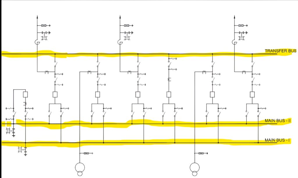
The limitation of the double main bus scheme can be overcome by using additional transfer Buses & breakers and isolators. In this arrangement, the feeder’s breakers, which are to be under maintenance are transferred to the transfer bus without affecting the power supply continuity. This scheme has been widely used for highly interconnected power networks where switching flexibility is important and multiple supply circuits are available.
Advantage:
Bus bar maintenance is possible without power supply interruption.
Disadvantage:
The scheme suffers from the disadvantage that at a time only 1 no. circuit breaker backup is possible & if at the same time problem in any other circuit breaker is raised, then the associated 2nd feeder must be under shutdown & power supply will be interrupted.
One & half breaker busbar scheme:
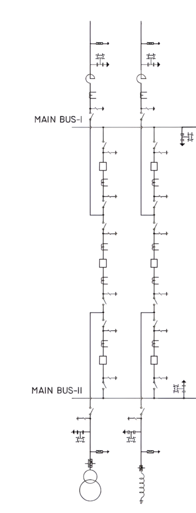
In this scheme, three circuit breakers are used for controlling two circuits. Normally, both the busbars are in service.
Advantage:
- The fault on any bus is cleared by the opening of the associated circuit breakers without affecting the continuity of supply.
- Any main bus can be taken out of service at any time for maintenance.
- Similarly, any circuit breaker can be taken out for maintenance without causing interruption & power supply is possible by the tie circuit breaker.
- Due to the involvement of the 3rd breaker power supply is possible without power interruption.
- In One & half breaker bus systems each circuit breaker must be suitable for carrying the currents of two circuits to meet the requirements of various switching operations.
- The breaker and half scheme is suitable for those substations that handle large amounts of power on each circuit. This scheme has been applied widely in 420 kV & 765 kV systems.
Disadvantage:
Due to the involvement of the third breaker, Cost is increased.
Switching schemes as per voltage levels
Switching schemes generally adopted as per different voltage levels in ais substations are listed below
Main and transfer bus or double bus scheme (with or without breaker bypass arrangement) | 66KV and 132KV |
Double main and transfer bus or double bus scheme (with or without breaker bypass arrangement) | 220KV |
One and half breaker scheme | 400 KV, 765 KV and above |
This article is a part of the Substation Guide, where other articles related to substation are discussed in details.
