A Current transformer is a type of instrument transformer that is used to step down the current of the primary side to a minimal value on the secondary side for ease of metering using standard ammeters and for protection purposes.
Table of Contents
As nowadays most relays are numeric and digital and hence need a very small current to it as input. The same is thus provided to them by a current transformer.
The current transformer finds its maximum usage in the power industry as without it no metering of energy and protection of equipment and lines will be possible.
Construction and Working
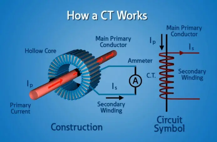
Unlike a power transformer, the current transformer consists of a single or very few turns in the primary winding. A single flat steel bar or a coil of heavy-duty wire or a single coil can shape up the primary winding. It is because of this the CT is also called a series transformer as the primary winding is in series with the current-carrying conductor.
The secondary winding moreover has a large number of turns wound around a low-loss magnetic core preferably silicon steel. For higher accuracy permalloy or mumetal alloy can also be used. The core has a large cross-sectional area and the winding is of a thin wire depending upon how much current has to be stepped down.
The secondary winding will feed current into the short circuit in the form of a connected ammeter or to a resistive load until a very large voltage induced in the secondary saturates the core and causes a failure from excessive voltage breakdown.
Unlike normal transformers, the primary current of the CT is not dependent on the secondary load but is controlled by an external load. The secondary current is generally rated at 5A or 1A.
Like any other transformer CTs have to satisfy the Amp-turn equation
TR=n=Np/Ns=Is/Ip, where p is primary and s is secondary.
The current ratio will set the turns ratio and as primary has single or very few turns, secondary can have several hundreds of turns. The current ratio between primary and secondary can be quite large.
Types of CT:
Wound type CT:
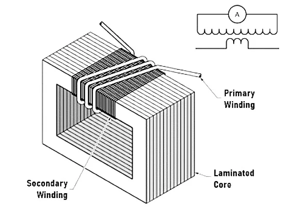
The transformer’s primary winding is physically connected in series with the current-carrying conductor whose values are to be measured. The primary and secondary windings are wound around a laminated core. These are mainly used to measure 1-100A current.
Bar type CT:
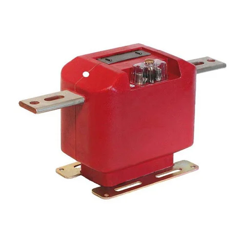
These transformers are equipped with only secondary winding. They utilize the bus bar or conductor which carries the current to be measured as primary winding, which is equivalent to a single turn.
Toroidal type CT:
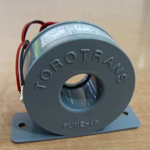
These do not contain primary winding. The current-carrying conductor is threaded to a hole or window in the CT. These have symmetrical shapes and due to this, there is low leakage flux and less electromagnetic interference. Some transformers have split cores and hence can be opened, installed, and closed without disconnecting the circuit.
Dry-type CT:
These utilize paper, resin, or pitch as solid insulating materials and are preferred in low-voltage applications.
Oil type CT:
These use oil as an insulating medium and are preferred for high-voltage applications.
Live tank CT:
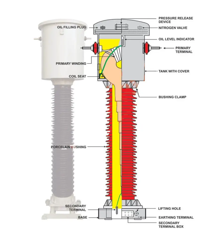
These have the tank at the top and the tank is at the same voltage level as that of the conductor. However the current flows through the primary tap only. The tank receives the same potential as the line via clamps. This design is however compact and as secondary runs through the porcelain insulator hence insulation is easy and economical.
Dead tank CT:

This has the tank at the bottom and thus the primary must be dropped up to the tank and requires good insulation. This design is bulky and costly.
LIVE TANK VS DEAD TANK CURRENT TRANSFORMER
| Aspect | Live Tank CT | Dead Tank CT |
| Construction | The tank which houses the core and secondary winding is live. | Longer, as it passes through the primary insulator |
| Primary Winding | Mechanically weak compared to Live tank due to not-so-good short-circuit and dynamic force withstanding capabilities. | Shorter, directly connected to the high voltage line |
| Insulation | Robust, due to shorter primary winding | Less robust, due to longer primary winding |
| Heat Dissipation | Better, primary winding in direct contact with oil | More heat generation during short-circuit conditions as partial primary winding is insulated in oil |
| Mechanical Strength | Higher, better against short-circuit forces | Mechanically weak compared to Live tank due to not so good short-circuit and dynamic force withstanding capabilities. |
| Applications | High voltage Level | Medium voltage Level |
Application of current transformers
Current transformers are used in substations, and industries for the purpose of measuring the flow of current in a feeder and protection purpose of the feeder.
Current transformers are also used for the metering and protection purposes of various power equipment like power transformers.
The current transformer also functions as a current limiting device which safeguards the relay and meters connected to its secondary.
Effects of CT secondary open-circuited:
If the CT secondary is open-circuited while the primary is still loaded then there will be no demagnetizing flux in the CT secondary due to which unopposed primary MMF will set abnormally high flux in the core. This flux will produce core loss with subsequent heating, inducing very high voltage in the CT secondary terminal. This high voltage will damage the insulation and excessive MMF leaves residual magnetism in the core affecting the future accuracy of CT. Therefore, the CT secondary shall never be open-circuited while loaded.
Errors of CT:
Current Ratio errors:
This error of CT is mainly due to the excitation current component. It is expressed as:
Ratio Error = (Kt * Ip – Is) / Ip, where Ip and Is are primary and secondary currents respectively and Kt is the turns ratio.
Phase angle error:
In an ideal CT, the phase angle between the primary and reversed secondary is zero. But in the actual case, the primary current also supplies the excitation current and hence there is a shift from the ideal case. This error is known as phase angle error.
Accuracy class of CT:
The accuracy class is designated by the highest permissible percentage of ratio error at rated primary current and rated output.
As per IEC61869-2, the standard accuracy class of CTs are: 0.1- used in labs, 0.2-0.2s for EHV application, 0.5-0.5s for MV application, 1 for LT voltage application, 3-5 are rarely used.
S is a special class. 0.2 class CT can measure with 0.2% error from 100-120% of the rated primary current, however, 0.2s class CT can measure with 0.2% error from 20-150% of the rated primary current.
Instrument Security Factor or safety factor (ISF):
At times of high fault current in the primary say 10KA and connected CTR is 200:1A, now the fault current in the CT secondary will be 100A but the connected wires and meters are not meant/rated to handle such high current.
Now if the ISF is 5 say, the CT’s core will saturate when the CT secondary current reaches 5 times the rate i.e., 5A. At the time of saturation output of the CT secondary will be constant or zero and thus the connected equipment will be saved.
As per IEC-61869-2 standard values are FS-5 & FS-10.
Common Issues of Current Transformers
- Insulation Failure: It may lead to a short circuit or disruptive failure of the CT. overheating, and oil leaks are predominant signs. However, in polluted areas, pollutants can cause a conductive path leading to insulation failure.
- Core saturation: This can be caused by a high burden at the secondary, high DC component in the primary current. It leads to incorrect secondary currents and failure in relay operations.
- Open CT Secondary: The causes can be corrosion in the secondary terminal which can lead to an open secondary lead in the CT terminal box or it can be caused by an open relay wiring issue. It raises the CT secondary voltage to dangerously high levels can can potentially cause CT failure.
- Oil leakage: Oil can be seen leaking from the CT which can cause insulation breakdown, overheating, and failure of the CT. It is usually caused when the seals are ruptured due to aging or any mechanical defect. Hence, it is essential to maintain the oil level of CT above the minimum level mark.
- Incorrect polarity ratio: It is usually caused due to faulty installation or manufacturing mismatch. It usually results in faulty metering and relay operation. It can be fixed by changing the CT secondary connections.
How can the performance of a current transformer be improved?
The performance of a CT can be improved by the following
- By using a core of high permeability and softer magnetic material, the hysteresis loss is lowered.
- By keeping the rated CT burden to the nearest possible actual burden.
- Ensuring a minimum length for the flux to flow and increasing the area of the path for flux.
- By reducing the internal reactance and resistance value to a bare minimum.
FAQ’s
How many cores can a Current transformer have?
A current transformer can have as many cores as required by a utility. 5 to 6 cores are required for Extra High voltage operations. One is used for Metering one for main 1 protection one for main 2 protection one for backup protection and others for redundancy purposes.
Can a current transformer have more than one ratio?
Yes, Current transformers can have more than 1 current ratio. They are called as multi ratio CT. It is just that tapping is taken out of the secondary at desired ratios.
What is the use of a core balance CT?
A core balance or CBCT is used in three-phase LT cables for identifying the zero sequence current or earth leakage current in the system. For single-core cables, all three cables must pass through CBCT. The CBCT secondary feeds a sensitive earth fault relay.
This article is a part of the Transformer page, where other articles related to the topic are discussed in details.

