TABLE OF Contents
A directional relay is one which is actuated by two electrical parameters namely current and voltage. The directional elements in the relay help the relay to recognize the direction of power flow based on phase angle comparison and isolate electrical faults in reverse the direction of normal power flow from the relaying point.
This feature can be best explained with the help of an electromechanical directional relay. It may be noted that directional elements are now embedded in digital relays in which electrical parameters are computed by microprocessors. Electromechanical relays are nowadays obsolete but it is helpful for understanding and explanation purposes.
WORKING PRINCIPLE OF DIRECTIONAL RELAY
Let us take an example of a directional relay electro-mechanical type. A diagram of the construction of the relay along with the phasor diagram is shown.
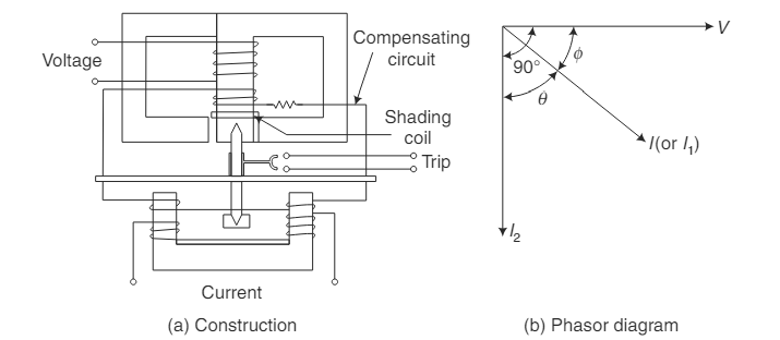
In an electromagnetic-type directional relay, two fluxes are being set up:
- Flux F1 is set up by the voltage from the PT, and
- Flux F2 sets up due to the current from the CT
Each flux induces an eddy current which when interacting with the opposing flux creates a torque. This torque either aids or opposes each other.
- Flux F1 induces an eddy current, interacts with opposing flux F2 generates a torque.
- Flux F2 induces an eddy current, interacts with opposing flux F1, and generates a torque.
The torque interaction generates a resultant torque on the disc which is proportional to VI cos Φ.
- V= Voltage
- I= Current
- Φ is the phase angle between voltage and current.
Maximum resultant torque is produced when the voltage and current are in phase. [i.e, Φ=0]
During fault conditions with a low power factor, when Φ becomes large, the resultant torque becomes minimum and the relay fails to operate. To counter this issue, compensating windings and shading coils are used in the electromechanical directional relay. These winding and coils maintain high sensitivity with effective fluxes during the fault.
For induction type relay, the torque is given by T= F1 F2 sin θ, where
- F1 and F2 are fluxes produced by I1 and I2, respectively.
- θ is the angle between the two fluxes F1 and F2
Voltage if assumed to be the actuator, then the current (I1) in the voltage coil lags behind the voltage by approximately 90°. The load current (I2) lags the voltage by angle Φ. Now from the phasor diagram, the angle θ between I1 and I2 becomes (90-Φ).
Here the voltage is a polarising quantity. The polarising quantity produces one of the two fluxes and therefore, is taken as a reference with respect to the current.
- The torque produced is positive when the value of cos Φ is positive, i.e. Φ is less than 90°.
- When Φ is above 90° (between 90° and 180°), the torque at the disc is negative.
To avoid tripping in the normal direction of the current two arrangements can be done:
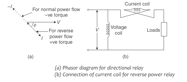
(i) When power flows in the normal direction at a particular relay location, the relay is connected to produce negative torque to avoid tripping. This is done by keeping the angle between the actuating quantities supplied to the relays at (180° – Φ) to produce negative torque. However, because of any reason if the power flow reverses, Φ is above 90° (between 90° and 180°) the relay will produce a positive torque and initiate a trip signal.
(ii) For the normal flow of power, the relay can be supplied with voltage (V) and negative current (I). For reverse power flow, the actuating quantities become V and I. Torque becomes positive that is = VI cos Φ. This is usually done by reversing the current coil connection leads.
In modern directional relays, the Current transformer and Potential transformer do the sensing of current and voltage. The phase angle determination and comparison are done by the microprocessor, digitally. Based on the phase angle the direction of power flow is determined. The generation of trip command is done by numerical computation at the digital relay if the power flow direction is sensed in reverse.
Directional Relay Connections
Whenever there is a close-in fault, the voltage drops, and at the directional relay, sufficient torque is not produced for the operation as one of the two parameters goes minimal. Also for certain fault conditions, the power factor [cos Φ] may also become low leading to insufficient torque production. These issues cannot be resolved with the normal connection of the relay.
Therefore, modifications in the terminal connection of the relay are to be practiced for sufficient torque production at the relay irrespective of types of faults and fault locations. Each relay therefore has to be powered by current from the respective phase and voltage from the remaining two.
There are two modes of connection practiced in the industry, one of them is the 30° connection, and the other is the 90° connection.
30° connection
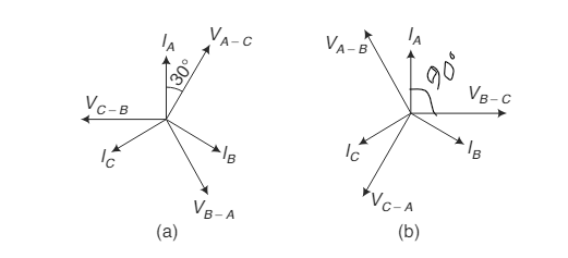
In the 30° connection, the phase A current coil draws phase current IA and line voltage VA-C. Similarly, the phase B coil is energized by IB and VB-A, and the same with phase C which is IC and VC-B. The maximum torque is produced when the current and voltage are in phase. This condition with the present connection is satisfied when the system power factor is 0.866 lagging.
90° connection
The 90° connection gives better performance under most circumstances. In this connection, the phase A coil of the relay is energized by IA and VB-C, the phase B coil by IB and VC-A, and the phase C coil by IC and VA-B. This connection develops maximum torque when the relay current leads voltage by 45° and has internal compensation. The phase angle sensed by the relay is always below 90° for all types of faults. This connection also provides excellent voltage polarization, but in the case of a three-phase close-up fault, the voltages on all phases become very small.
The 90° connection provides better performance than the 30° connection for symmetrical three-phase faults.
APPLICATIONS OF DIRECTIONAL RELAY
Directional relays are used in the protection of parallel feeders. Figure shows a directional overcurrent protection scheme. Here A and B are the sending end breakers using a nondirectional relay, and C&D are receiving end breakers using a directional relay. For a fault at F, B will trip because it’s a nondirectional relay, and D will also trip because the direction of current at the relay element is reversed. However, the breaker at C will not trip because the current is flowing in the normal direction in the relay. Thereby isolating the faulty section while the healthy section remains alive.
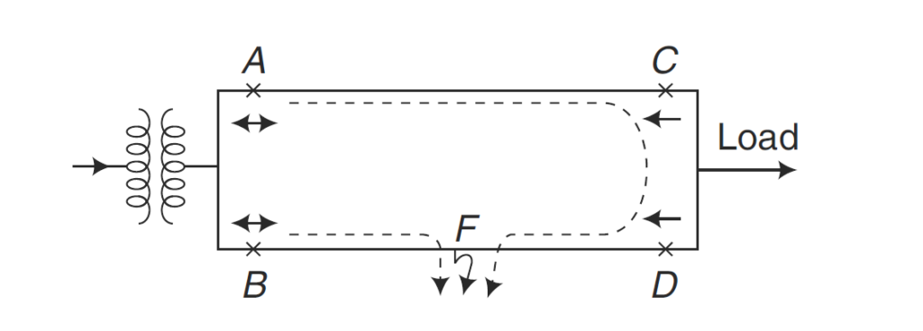
Similarly, directional relays can be used for protection in the ring main and radial feeders.
FAQ’s
What is the advantage of using a directional relay?
The main advantage is that the directional element in the relay can sense the direction of power flow and by utilizing it, only the faulty section of the power system can be isolated which essentially feeds the fault. It improves the selectivity of the protection system.
Is there a directional distance relay?
Yes, the directional element can be integrated with distance and differential relays, this integration helps in busbar protection.
This article is a part of the Protection System, where other articles related to the protection of electrical equipments are discussed in details.

